Circuit Guidelines
A number of different electrical configurations are available in feedthrough filters, including the common types shown opposite. A single element filter (a capacitor or an inductor) theoretically provides an insertion loss characteristic of 20dB per decade, a dual element filter (capacitor/inductor) 40dB per decade whilst a tiple element filter (Pi or T configuration) theoretically yields 60dB per decade. In practice, the insertion loss curves do not exactly match the predictions, and the data sheets should be consulted for the realistic figure. The choice of electrical configuration is made primarily on the source and load impedances and may also be influenced by the level of attenuation required at various frequencies.
C-Filter (Capacitive)
The C filter is a three terminal feed-through capacitor. It is used to attenuate high frequency signals. Instec filters employ multi-layer ceramic discoidal capacitors. These offer the best attenuation due to a circumferential metallization’s with infinite paths to ground. MLCC discoidal capacitor designs offer superior performance over chip capacitor and tubular capacitor designs. In the case of the latter, the discoidal cap is much more robust and in the case of the former, the discoidal has the advantage of circumferential metallization’s. This filter should be avoided for use in circuits where large voltage transients occur in favor of a circuit which includes inductive elements.
- Consists of a feed-thru discoidal capacitor (multilayer) inserted between transmission line and ground
- Theoretical attenuation is approximately -20dB/decade
- Suitable for applications where source impedance is high (≥1Ω) and where sharp cut-off (steep slope of insertion loss curve) is NOT required.

L-Filter
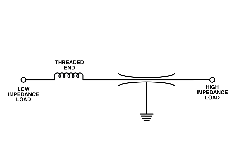
The L filter is a three terminal filter consisting of one inductive element and one capacitive element. Instec’s design of L filters also employ the MLCC discoidal capacitor for the capacitive element providing the same superior performance described in the C-Filter description above. The inductive element may be a ferrite bead or a toroid, depending on the Insertion Loss requirements, the current rating, and the space available. L filters can offer high or low impedance depending on their orientation in the circuit. These filters are most commonly used in applications where there is a high impedance source and a low impedance load (L1) or where there is a low impedance source and a high impedance load (L2).
- Consist of a single capacitive element and single inductive element
- When choosing, the inductive element should be to the side with the lower impedance.
- Theoretical insertion loss is -40 dB/decade
- L-Filters are ideal for circuits where source and load impedances are different


PI-Filter
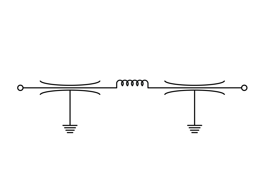
The PI filter contains two capacitive element separated by an inductive element. Instec’s design of PI filters also employ the MLCC discoidal capacitor for the capacitive element providing the same superior performance described in the C-Filter description above. The inductive element may be a ferrite bead or a toroid, depending on the Insertion Loss requirements, the current rating, and the space available. PI filters present low impedance to both the source and the load and provide better high frequency performance that the C or L configurations. Due to the possibility of resonance, PI filters are not recommended for switching applications.
- Consists of two discoidal capacitors separated by one inductive element
- PI – Filters are best suited in circuits with low impedances (typically ≤1Ω)
- Theoretical insertion loss is -60dB/decade
- Dissimilar impedances between source and load do not materially affect performance.

T-Filter
The T filter consists of two inductive elements separate by a capacitive element. Instec’s design of T filters also employ the MLCC discoidal capacitor for the capacitive element providing the same superior performance described in the C-Filter description above. The inductive element may be a ferrite bead or a toroid, depending on the Insertion Loss requirements, the current rating, and the space available. T filters present high impedance input from either side and can be sued in applications where transient conditions may occur. It has similar filtering performance to a PI circuit without the resonance characteristic of a PI filter. They may therefore be used in switching applications.
- Consist of a single capacitive element between two inductive elements
- Theoretical insertion loss is -60 dB/decade
- T-Filters are best suited in circuits with low impedances (typically ≤1Ω)
- Dissimilar impedances between source and load do not materially affect performance.
- Usable in switching applications

T-T-Filter
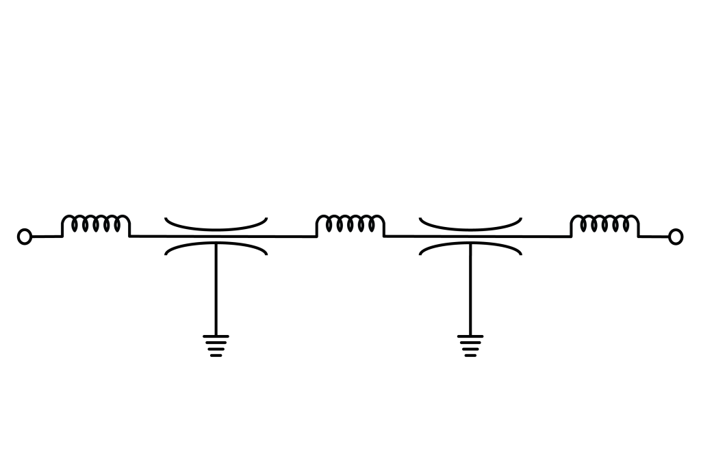
The T-T filter, or multi-element filter, consists of three inductive elements separated by two capacitive elements. Instec’s design of T-T filters also employ the MLCC discoidal capacitor for the capacitive element providing the same superior performance described in the C-Filter description above. The inductive element may be a ferrite bead or a toroid, depending on the Insertion Loss requirements, the current rating, and the space available. T-T filters are designed for optimum insertion loss in circuits with relatively low source and load impedances, as well as applications where a high degree of filtering is required.
- Consist of three inductive elements separated by two discoidal caps
- TT-Filters designed for optimum insertion loss in circuits with low source and load impedances
- Used in applications with a high degree of filtering

